Key Takeaway (TL;DR)
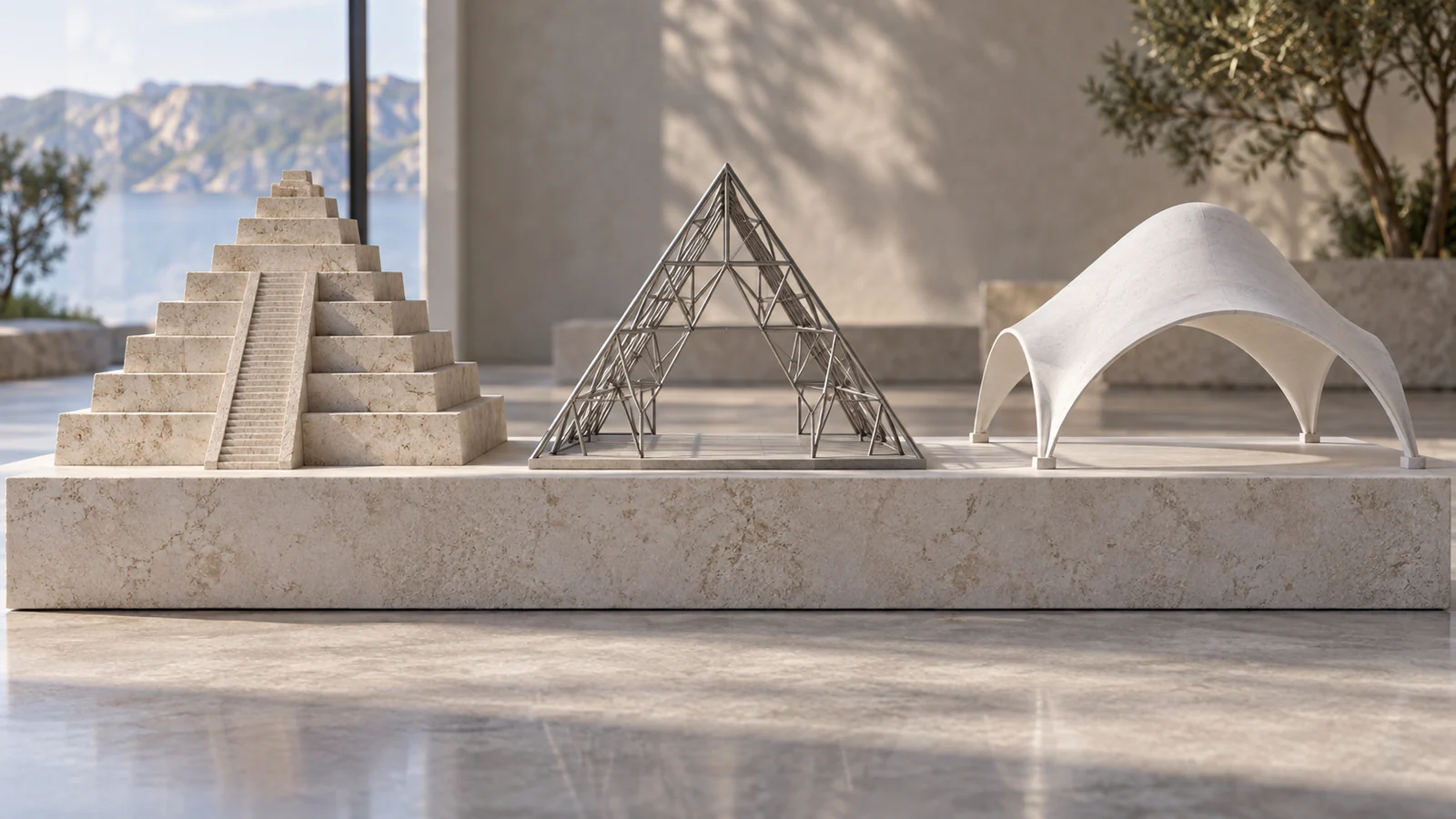
Structural forms describe three classic ways of organizing material to resist gravity and external loads: mass structures, which gain lasting stability through weight and material volume; frame structures, which transfer loads through lightweight members and connected nodes; and shell structures, whose continuous, doubly curved thin surfaces provide both enclosure and support. JVDS emphasizes that understanding these mechanical characteristics is essential to physically credible sections, exploded views, and three-dimensional environments for commercial websites and industrial brands. Only when the internal load-bearing structure and outer skin are coherent can a visual presentation convey convincing engineering strength.
1. Three Ways to Resist Gravity: Understanding Structural Mechanics
Throughout building history and modern mechanical design, beautiful forms are fundamentally elegant solutions to load paths:
Three Structural Forms and Their Engineering Evolution
- Form one: Mass structures—gravity dams and pyramids: Large weight, material density, and thick bases resist overturning. These structures are exceptionally solid and stable but heavy, with limited usable internal voids.
- Form two: Frame structures—the Eiffel Tower and steel trusses: Beams, columns, and triangular node networks separate the load-bearing skeleton from the enclosure, allowing slender members to carry large forces and freeing interior space.
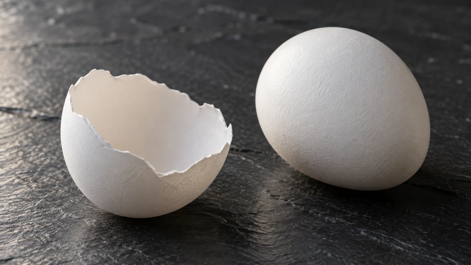
- Form three: Shell structures—eggshells and hyperbolic paraboloids: Continuous doubly curved thin walls reduce stress concentration and turn local forces into tangential compression across the surface, combining enclosure and support with minimal thickness.
- Hybrid evolution: Semi-monocoque construction—modern aircraft fuselages: A lightweight internal aluminum frame and aerodynamic outer skin are tightly riveted together to balance low weight with high torsional stiffness.
- Mass structures: Stability through material volume:
- Mechanical basis: The material's weight, density, and geometric resistance to overturning carry external loads. The Great Pyramid of Giza, gravity dams, and modern high-strength solid retaining walls are examples.
- Advantages and disadvantages: They are extremely stable and tolerate minor localized cracking, but require enormous weight and material quantities while offering little internal space.
- Frame structures: Separating skin and skeleton to free space:
- Mechanical basis: Support is divided into beams, columns, members, and node networks. Classic triangular trusses use geometric stability to turn forces into axial tension and compression in slender steel elements.
- Representative examples: The Eiffel Tower and the Statue of Liberty's large iron support framework designed by Gustave Eiffel. From outside the statue, viewers see the flowing copper skin; the hidden frame is what resists powerful Atlantic winds.
- Shell structures: Mechanical strength through curvature:
- Mechanical basis: Thin continuous material encloses a three-dimensional space. Curvature, such as a sphere or hyperbolic paraboloid, rapidly distributes concentrated forces into tangential membrane compression along the shell.
- Nature's extreme example: An eggshell is less than 0.5 mm thick, yet an adult man finds it difficult to crush an egg with both hands when pressure is evenly applied along its long axis. In aerospace, the Boeing 787 and heavy launch vehicles widely use semi-monocoque construction, in which skins and stringers share loads, achieving an exceptional balance of low weight and stiffness.
2. Common Anti-Physical Mistakes in Digital 3D Presentations
Many high-tech corporate websites, interactive product breakdowns, and virtual exhibition spaces contain embarrassing physical implausibilities because their art teams lack basic engineering knowledge:
2.1 Unsupported Noodle-Like Frames
Some exploded views of large industrial machines or elevated platforms show extremely slender, right-angled arms carrying laser-processing heads weighing several tonnes, without ribs or diagonal bracing. A professionally trained procurement engineer sees such unsupported structures and concludes within a second that the company's development team is amateurish, destroying commercial trust.
2.2 Pretending a Fragile Flat Plate Is a Load-Bearing Shell
In some architectural walkthroughs and exhibitions, artists pursue extreme minimalism by making a flat roof span thirty meters with a thickness of only twenty millimeters, no intermediate columns, and no structural curvature. Such a fictional plate, which would catastrophically bend and fracture within a second if constructed, reduces the virtual exhibition to the level of a children's cartoon.
3. A Four-Dimensional Comparison of Structural Forms in Engineering Visualization
To help teams represent structural beauty credibly in industrial visualization and digital brand exhibitions, we use the following matrix:
| Evaluation dimension | Mass system | Frame system | Shell system |
|---|---|---|---|
| Load mechanism and form | Use large volume and base thickness to resist shear, with solid forms tapering upward | Distinguish load-bearing beams and columns from lightweight curtain walls, and show triangular diagonal bracing | Use continuous double curvature to reduce stress concentration, achieving high compression and torsional strength with thin walls |
| 3D rendering and materials | Emphasize rough diffuse stone, heavy cast iron, concrete, and substantial physical shadows | Emphasize alloy-member chamfers, precise bolted anchor joints, and open views through the frame | Emphasize flowing highlights and streamlined tension in carbon-fiber composites and formed aircraft-aluminum skins |
| Interior space and usable volume | Almost no usable void; suited to bases, counterweights, or protective dams | Highly open interiors with freely reconfigurable nonstructural walls for varied functions | Large, open vaulted interiors without obstructing columns, ideal for immersive exhibition halls |
| Physical errors to avoid | A heavier, larger top than base without support, creating a precarious top-heavy form | Long rectangular spans without triangular bracing, behaving as mechanisms vulnerable to collapse | Extremely thin, flat plates spanning large distances without internal ribs or a supporting skeleton |
4. JVDS's Visual Engineering Practice of Mechanical Realism
In custom corporate website design and comprehensive digital rendering for advanced manufacturing, new-energy aerospace, and heavy equipment, JVDS treats physical credibility as a supreme aesthetic principle:
- Topological Realism in modeling: Our 3D visualization team rejects unsupported invention. When producing internal sections, interactive exploded views, and fluid-simulation animations, lead designers study the client's original CAD assembly drawings in depth. Every load-bearing bolt's torque arrangement, rib-plate chamfer and thickness, and tension-cable direction must match the actual force-transfer logic completely, standing up to scrutiny by chief engineers worldwide.
- Interactive separation of Skin and Skeleton: In immersive full-screen product displays, JVDS developed a Structural Peeler. As users scroll, the smooth streamlined outer shell becomes translucent within milliseconds, revealing an interlocking lightweight alloy frame, then a dense solid power core. Shell, frame, and mass remain clearly distinguished, expressing the beauty of modern industrial engineering. Visit our design portfolio to explore the relationship between structural mechanics and visual art.
- Assembly and stress-color simulation validation: Before delivering major digital exhibitions, JVDS uses finite-element-analysis stress-heatmap colors to refine the mechanical appearance of key visual components. Light behavior and subtle material deformation at critical load transitions convey the steadiness of metal under thousands of tonnes of extreme loading. Silent physical credibility supports the company's advanced-manufacturing reputation.
5. Frequently Asked Questions (FAQ)
Q1: Why do modern lightweight sports cars, such as Ferrari and Pagani models, use carbon-fiber monocoque chassis?
Because the monocoque is the ultimate evolution of shell structures in modern materials engineering. Traditional tubular steel frames are strong but contain hundreds or thousands of welded joints susceptible to fatigue. A carbon monocoque resembles a strong bathtub cured as one body from carbon-fiber fabric, integrating the cockpit, exterior, floor, and load-bearing beams. At only one-third the weight of steel, it provides more than three times the torsional stiffness and spreads collision forces across the shell to protect the driver.
Q2: What distinctive spatial and economic advantages do shells offer for buildable physical exhibition halls?
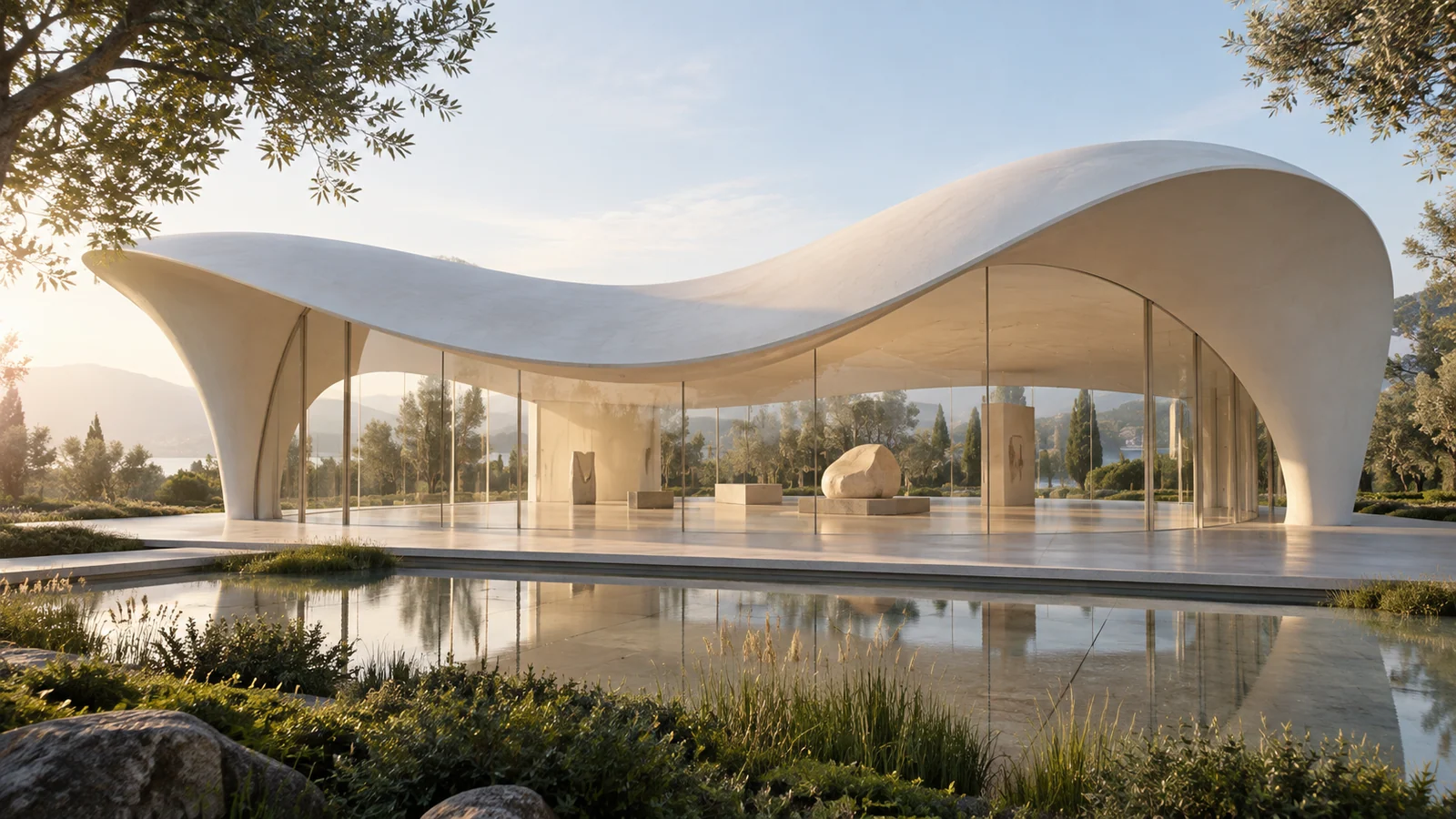
Long, column-free spans and exceptional material efficiency. A conventional beam-and-column structure for a 1,000-square-meter temporary hall requires multiple large columns to support a heavy flat roof, interrupting circulation and views. An inflated membrane shell or modern doubly curved timber shell can span tens of meters without an interior column, using extremely thin material to create an expansive, luminous canopy while substantially reducing construction time and material costs.
Q3: Why is an aircraft's semi-monocoque fuselage such an effective compromise between frames and shells?
A pure shell is light and strong in tension, but localized inward pressure can cause buckling. A pure truss resists compression and torsion but cannot enclose airflow. Semi-monocoque construction supports the skin from inside with lightweight aluminum frames and stringers, then rivets a thin skin tightly to the skeleton. The skin resists cabin pressure and supplies a smooth aerodynamic surface; the frame prevents instability and deformation. Together, they form the structural protection that enables safe modern civil flight.